


 In metallic structures it is common to use bolted joints with drilled holes (through holes) to allow free expansion of the elements under thermal loads. It is interesting to analyze how this behavior can be modeled in a structure as a whole as a function of free expansion(e).
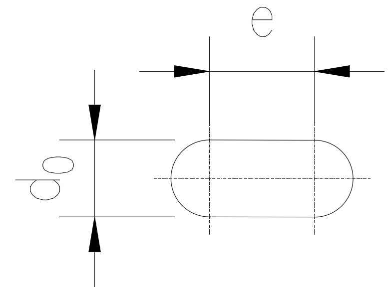
Figure 1 – Ripped bore of diameter d0 and free length e.
The natural design process should be as follows:
- Calculate the maximum expansion displacement of the structure that would affect the joint in question.
- Based on the above calculation, determine the length e sufficient to allow free expansion.
If this were the case, it is already known that the element in question can expand freely and the modeling of this behavior only involves releasing the constraint on longitudinal displacement (applying a release). Conceptually, the modeling of a biaxially supported beam subjected to uniform temperature would be as follows:
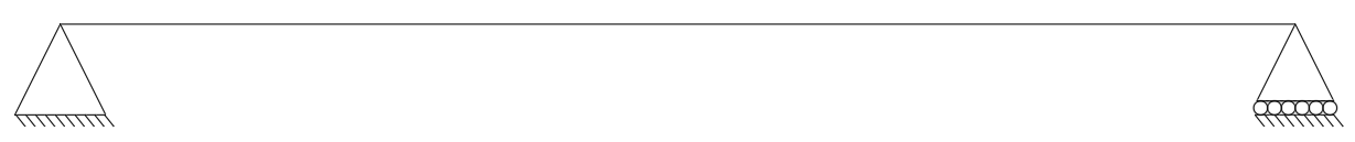
Figure 2 – Conceptual modeling of a two-legged beam with free expansion allowed at one end.
However, it is common that the characteristics of bolted joints are imposed by standards, which may cause the dimension e to be insufficient. That is to say, it may happen that the bar tries to expand more than what the joint tearing allows. In this case the behavior of the free expansion support has two modes:
- Free expansion as long as the longitudinal displacement (u1) is less than e.
- Restriction of longitudinal displacement (and consequent occurrence of compressive stresses) when u1=e.
The conceptual scheme would be as follows:
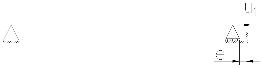
Figure 3 – Conceptual modeling of a two-legged beam with longitudinal displacement partially allowed in one of its supports.
Let’s take an example:
A biaxially supported bar is subjected to a temperature increase of 72 0C (300 due to ambient temperature and420 due to solar radiation) with respect to the installation temperature. The bar has an IPE220 profile, is made of S275 steel and the total length is 20m. At one end, the support allows a displacement of 1 cm.
The longitudinal expansion in a member in the case of no restraints is calculated as follows:
ΔL=αL-ΔT-L
Being:
ΔL: Uniform temperature elongation.
αL: Coefficient of linear expansion of the material.
ΔT: Temperature increase.
L: Initial length of the bar.
Thus, the following result is obtained:
|
L (m) |
20 |
|
aL (0C-1) |
1.20E-05 |
|
DT(0C) |
72 |
|
DL (cm) |
1.73 |
Table 1 – Free deformation due to expansion.
Since the deformation allowed by the support is 1 cm, the bar will undergo two processes:
- It will dilate freely until it has elongated 1 cm without stress.
- It will stop expanding and will undergo the axial compressive stress corresponding to the attempt to expand the 0.73 cm that the support does not allow.
The stress produced is the equivalent to the stress suffered by the bar when it is shortened by 0.73 cm.
It is easy to obtain this axial force by classical strength theory:
|
L (m) |
20 |
Profile |
IPE220 |
|
|
aL (0C-1) |
1.20E-05 |
A (cm2) |
33.4 |
|
|
DL (cm) |
-0.73 |
E (MPa) |
210,000 |
|
|
|
|
e |
3.64E-04 |
|
|
|
|
N (kN) |
-255.31 |
|
|
s (MPa) |
-76.44 |
|||
|
fy (MPa) |
275 |
|||
|
s / fy |
27.80% |
Table 2 – Calculation of the axial force produced when the bar has expanded as much as the support allows.
The stresses caused by the applied restraint correspond to almost 30% of the elastic limit, so they are by no means negligible.
What this simple example demonstrates is that significant design errors would be incurred if this structure were modeled either with free longitudinal displacement at one of its ends, or with such displacement restricted at both supports.
This is a non-linear behavior (since it has two different phases, the behavior loses its linearity) simple to understand and calculate in cases as simple as the one presented here, but in many situations it is a problem for its modeling in structural calculation programs.
So how do we model it in a calculation program?
The way to solve this type of problem is usually to use a gap element and perform a nonlinear analysis. The conceptual scheme of this element is as follows:
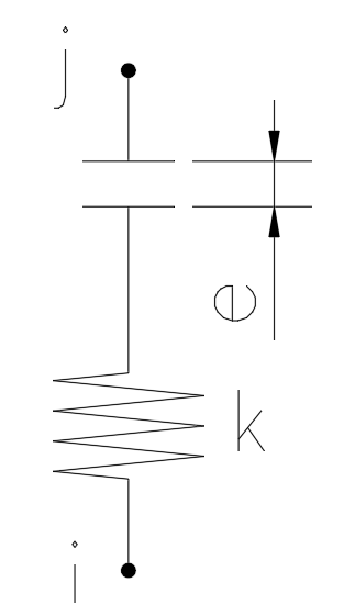
Image 4 – Conceptual diagram of a gap element.
The force ratio (f) – deformation (def) of this element in one direction is given by:
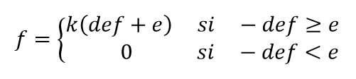
Being def negative if it is a shortening.
This element has many applications and is very useful in a number of practical cases. For the case we are concerned with here, the parameter e corresponds to the length of free deformation that exists at the joint, while the stiffness can be taken as infinite (a few orders of magnitude above the stiffness of the structure). That is, with this configuration we would allow the approach of nodes i and j until the gap is closed. From that moment on, no further shortening is allowed.
In the SAP2000 software, the gap element is included in the link type elements. Thus, when defining the characteristics of a link we can configure it to act as explained above.
Below is an outline of the process for creating a gap link to model the example studied above.
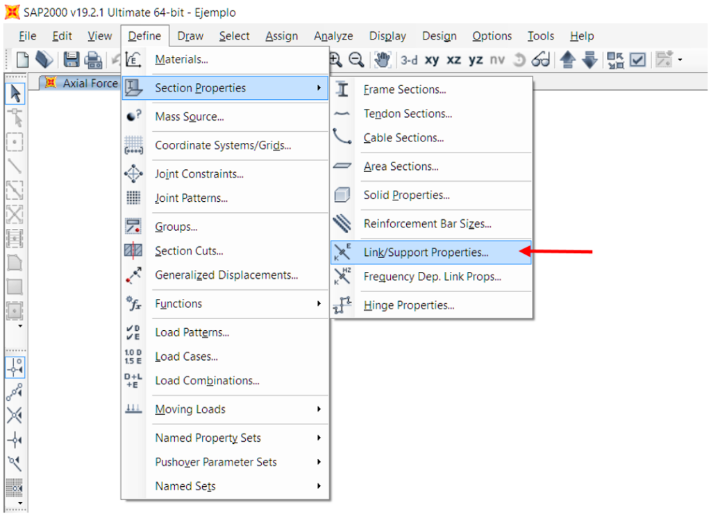
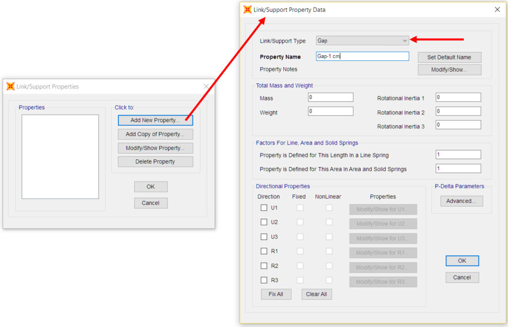
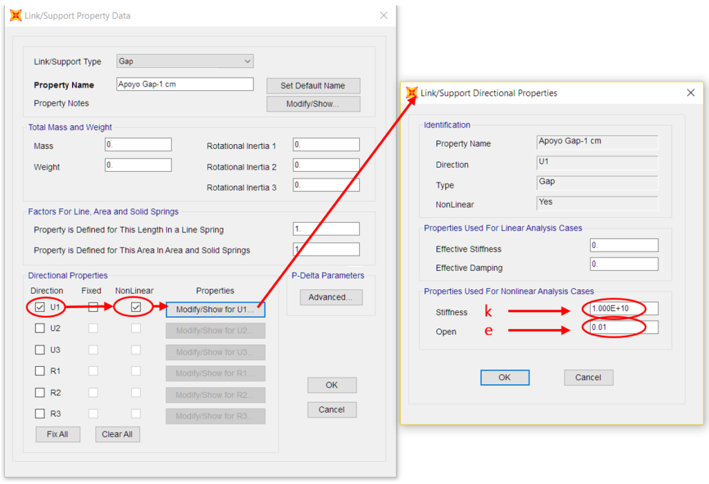 Figure 5 – Process to configure a gap element in SAP2000.
To define a stiffness that does not allow displacement beyond the length e, it is not recommended to use an exaggeratedly high value, but a value between 1 and 3 orders of magnitude greater than the stiffness of the neighboring elements. Values that are too high may result in the generation of singular matrices.
Once the element is defined, the geometry and external links of the previous problem can be configured as follows:
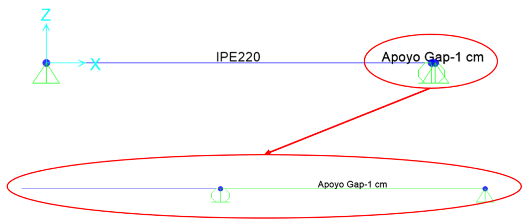 Figure 6 – Support configuration with gap element in longitudinal direction.
This configuration is only one of the possible configurations. As can be seen, the longitudinal displacement in the real support has been released, and another fictitious support has been created outside the structure. Between these two supports, the gap element (2-joint link) is placed, which will only allow the displacement of 1 cm in X direction in the real support.
Once the geometric configuration is created, the720 temperature settings are applied on the member and the affected load case is configured as NON-LINEAR. In those load cases that are not defined as NON-LINEAR, this link will have no impact.
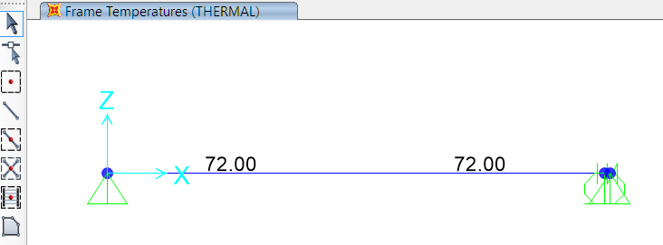 Image 7 – Temperature applied to the bar.
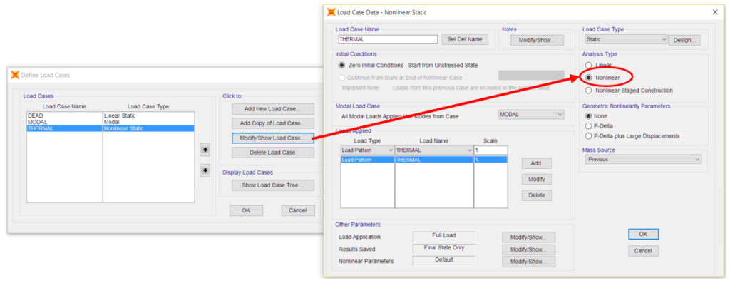 Figure 8 – Configuration of load cases as NON-LINEAR.
Once this configuration has been implemented and the calculations have been carried out, the results obtained in terms of stresses and deformations are the same as those previously calculated:
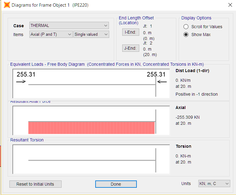
Figure 9 – Diagram of stresses in the member (axial force of -255.31 kN).
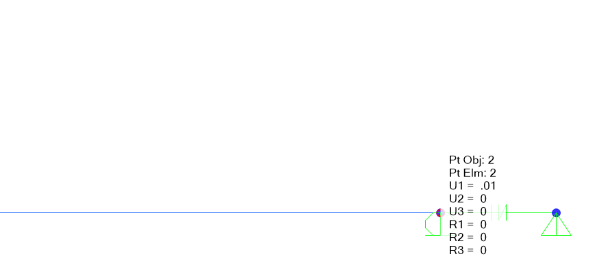 Image 10 – Displacements in extreme support (1 cm).
This is perhaps the simplest case of application of the gap element, however, it is sufficiently illustrative to show the possibilities of the element. By defining the link we can implement the behavior of an independent gap in each degree of freedom, or fix all the movements in the l.d.g. we are interested in, etc. Thus, it can be very useful whenever there is a gap that we think is important to treat in our structure.
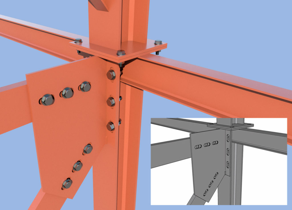
For example, in the following figure it has been used to model the gap between two parts of a platform resting on the same column. In this particular case, if the gap-type link is not included, each platform moves longitudinally without taking into account the “collision” with the adjacent one. In the configuration of this element, the vertical and transverse displacements to the platforms were fixed, according to the characteristics of the real supports.
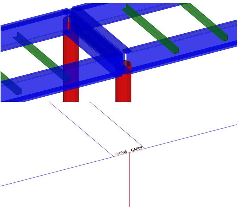
Image 11 – Example of the use of gap type elements.
More interesting examples can be found in the following link (in this case to take into account adjacent but slightly separated buildings that may influence the dynamic calculation).
There is also an element to model the opposite, holes that can be opened up to a certain length, these are the hook elements.
I hope this post can be useful and see you soon!


