


At Civile we like to face new challenges every day!
We are aware that our main market niche in the field of structures has to do mainly with structures oriented to industry and building (foundations of equipment and tanks, industrial buildings, single-family houses…). For this reason, when we receive a structure outside these typologies, we try to approach it with the greatest possible enthusiasm and care.
Structural design of an ornamental statue
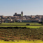
In this case, we come to present a unique structure calculated by our technicians in recent months. It is an ornamental statue made of Corten steel located in a traffic circle, having previously studied that it does not pose a problem of visibility or circulation to be located in the center of the same and without a height that can be considered excessive.
Description of the structure
The structure (in the shape of a world ball) consists of a sphere-shaped metal framework with a diameter of 8 m, which is covered with 925 metal elements of 4 mm thickness.
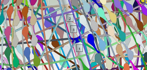
Image 1 –> Discretization of metallic elements.
The sphere is supported on an inclined axis which in turn is embedded in its upper and lower part on a crescent. Inside there are metallic elements that give it rigidity in the form of radii, meridians and parallels.

Image 2 –> Steel sections used.
How was it calculated?
The following calculation software was used for modeling the structure, obtaining stresses and sectional dimensioning:
Autodesk Robot Structural Professional.
The analysis of the structure is carried out by means of finite elements. For the linear elements (steel bars), beam elements are used. For the sphere sheet, shell elements are used, which distribute the load according to their corresponding tributary areas.
The hypotheses taken into account are the following:
- Generation of own weight of the bars: It is obtained automatically from the geometry and the specific weight of the steel.
- Generation of the dead weight of Corten steel elements. It is obtained by assigning an equivalent thickness to the sheet so that its resultant coincides with the total weight.
- Generation of wind loads: Based on the parameters described above, wind loads are generated for different directions, not concomitant with each other, looking for the most unfavorable case.

Image 3 –> Wind pressure generation.
In conclusion, it should be noted that this work has taken us out of our comfort zone but, even so, it has been equally rewarding and we feel eager to take on work like this again as many times as necessary.
Don’t miss the rest of CIVILE’s blog posts!
Written by:
Marina García Pintor
Civil Engineer
Area of Civil Engineering and Architecture


